Wheel Odometry
Dead reckoning: core nav for mobile robots and AGVs. Track wheel turns from a start point for tight short-range moves.

Core Concepts
Rotary Encoders
Encoders on motor shafts turn rotation into pulse counts for exact wheel tracking.
Dead Reckoning
Dead reckoning: estimating position from last known spot plus speed and time.
Kinematic Modeling
Kinematics math turns wheel speeds into robot's real-world speed and turns.
Differential Drive
A popular steering setup that controls movement by adjusting the speeds of two wheels powered independently on the same axle.
Drift & Error
Tiny measurement errors that pile up over time from things like wheel slip, bumpy floors, or tires squishing under load.
Pose Estimation
The key output from odometry: a steady, ongoing estimate of the robot's position (x, y) and heading (theta).
How It Works
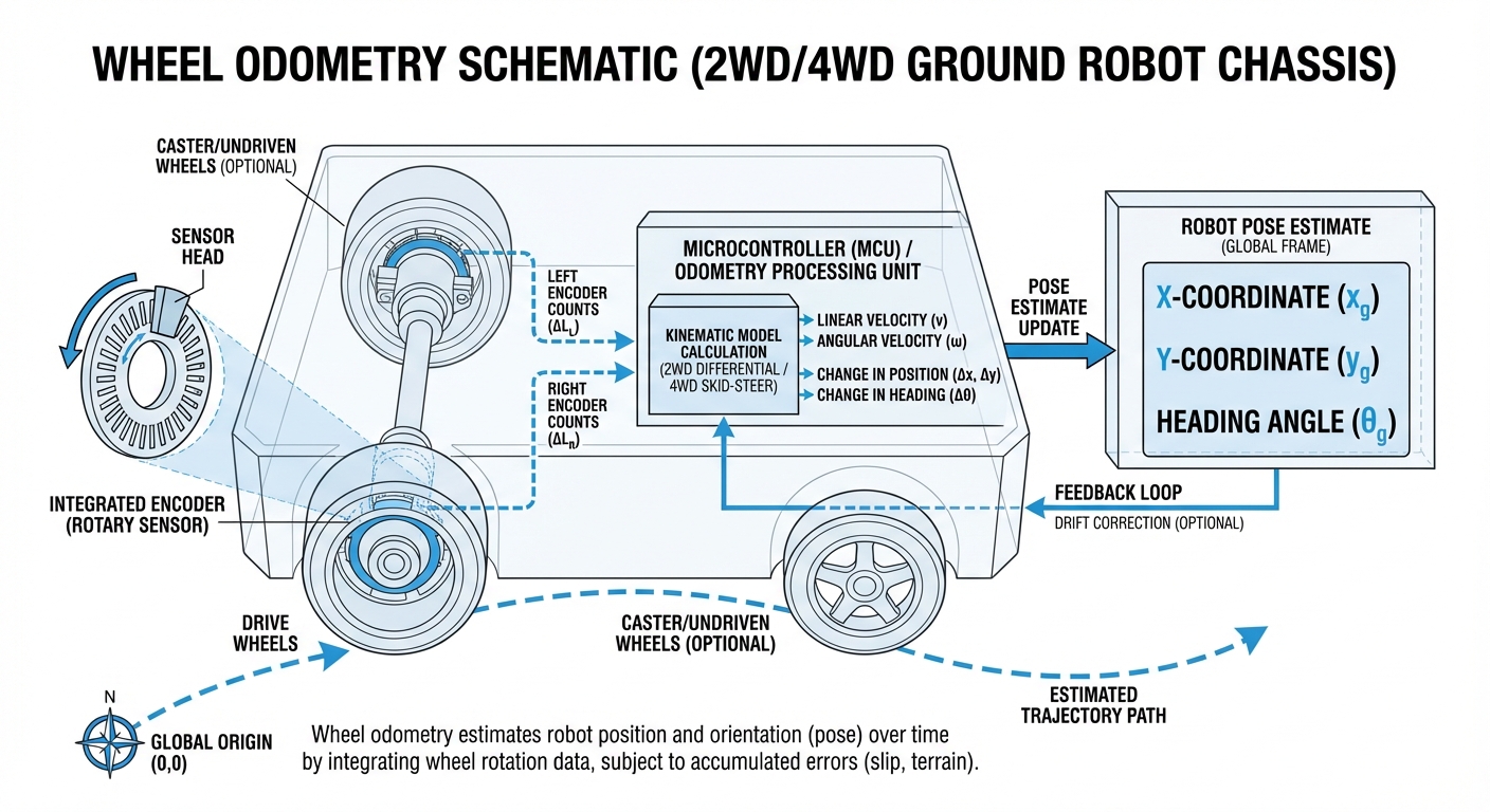
Wheel odometry works by adding up velocity readings over time. On a differential drive AGV, sensors on the left and right wheels tally 'ticks.' With the wheel radius and encoder resolution in mind, the system figures out how far each wheel has rolled.
If both wheels cover the same ground, the robot goes straight. Any difference, and it turns. The system crunches these to get linear velocity ($v$) and angular velocity ($\omega$).
These speeds feed into a kinematic model—updated hundreds of times a second—to refresh the robot's position estimate ($x, y, \theta$). It's spot-on for short hauls, but needs extras like IMU or LiDAR to fix drift over longer runs.
Real-World Applications
Warehouse Logistics
AGVs lean on odometry to weave precisely between tight storage racks where GPS won't cut it. It nails smooth turns and perfect docking at charging stations.
Autonomous Cleaning
Commercial floor scrubbers use odometry to map out full coverage without missing spots or doubling back.
Hospital Delivery
Service robots zipping linens or meds down hospital halls count on odometry for the smooth position data that powers obstacle avoidance.
Manufacturing Assembly
In car assembly lines, mobile platforms haul hefty chassis, and high-res wheel odometry keeps them perfectly synced with the line speed.
Frequently Asked Questions
What's the difference between visual odometry and wheel odometry?
Wheel odometry taps wheel sensors to track rotations and distances. Visual odometry uses cameras to follow environmental features for motion estimates. Visual shines at fighting long-term drift, but wheel odometry is quicker, lighter on compute, and thrives in the dark or blank spaces.
Why does wheel odometry drift over time?
Drift builds because errors stack up. Small slip-ups from wheel spin, uneven surfaces, off tire pressures, or wonky alignment get integrated over time. Without a reset from LiDAR or GPS, even 1% error means meters off after a long trek.
What type of encoders are best for AGV odometry?
Quadrature incremental optical encoders rule AGVs. They deliver thousands of ticks per turn plus direction info. For instant absolute position at startup—no homing needed—magnetic absolute encoders step in, though they cost more.
How does wheel diameter affect odometry accuracy?
Wheel diameter is fixed in the kinematic math. But if tires wear down or compress under weight, each turn covers less ground than expected. Routine radius tweaks keep things accurate.
Can wheel odometry work on Mecanum wheels?
Sure, but the equations get trickier. Mecanum wheels go every which way, so the model factors in roller forces. Plus, they slip more than regular tires, so odometry gets noisier over distance.
What is the typical sampling rate for odometry calculations?
Modern mobile robots crunch odometry at 50Hz to 100Hz—50 to 100 times a second. Faster bots might push higher. This keeps control silky smooth and reactions lightning-quick.
How is wheel slippage handled in software?
Straight wheel odometry misses slips like spinning on oil. Pros fuse it with sensors (often Extended Kalman Filters), cross-checking wheels against IMU accel/gyro data. No accel despite wheel spin? Slip detected—switch to IMU.
Is wheel odometry sufficient for autonomous navigation?
Rarely solo. It's great for quick hops or blind straights, but full autonomy pairs it with LiDAR (SLAM), Visual SLAM, or tape/QR codes to zap drift against the real map.
What’s the 'Wheelbase' parameter, and why does it matter?
Wheelbase is the gap between left and right wheel contact patches. It's make-or-break for turns. Even a millimeter mismatch between software and reality throws off every rotation with systematic heading errors.
How do I calibrate my robot's odometry?
A go-to test is UMBmark: drive a 4m square. Measure start-to-end offset to dial in fixes for wheel diameter and wheelbase, tuning your kinematic model sharp.
Does the floor surface affect odometry performance?
Big time. Carpets add drag and slip. Slick concrete slides. Bumps lift wheels. Hard, flat, grippy floors like concrete or tiles are ideal.
How is odometry data typically transmitted?
In ROS, odometry publishes as standard messages with Pose (position/heading) and Twist (velocities), plus TF transforms from `odom` to `base_link` frame.
Ready to implement Wheel Odometry in your fleet?
Our newest AGVs pack high-res industrial encoders and smart sensor fusion for accuracy down to sub-centimeter.
Explore Our Robots